
Blog

How to Optimize Aluminium Heat Dissipation?

Efficient Aluminium Heat Dissipation is essential for protecting components, improving reliability, and extending service life. In practical systems, heat rarely moves as neatly as design drawings suggest. A compact enclosure, dusty surface, or poorly fitted interface can raise operating temperatures within minutes.

This guide examines how to optimize Aluminium Heat Dissipation through material selection, surface area, airflow, and thermal interface quality. Aluminium offers low weight, good thermal conductivity, and flexible manufacturing options. However, thicker aluminium does not automatically guarantee better cooling. Fin geometry, contact pressure, coating, and orientation can matter just as much. Small details matter.

Reliable optimization begins with measurable evidence. Engineers should record component power, ambient temperature, surface temperature, and airflow conditions before changing the design. Infrared cameras can reveal hot spots, but emissivity settings may distort readings. Thermocouples provide useful confirmation when installed carefully. Neither method is perfect.

The discussion also considers passive and active cooling methods. Natural convection may suit low-power electronics, while fans or heat pipes can support higher thermal loads. Trusted engineering references, manufacturer data, and controlled testing should guide final decisions. A design that performs well in a laboratory may struggle inside a sealed cabinet or under seasonal temperature changes. That limitation deserves attention.

Good thermal design is not about choosing the largest heat sink. It is about balancing conductivity, geometry, cost, weight, maintenance, and real operating conditions. Some recommendations will need adjustment after testing. That is normal. Careful measurement turns uncertainty into a dependable cooling strategy.
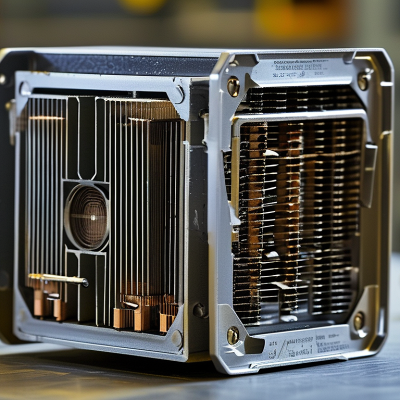
How to Optimize Aluminium Heat Dissipation?

Aluminium’s Thermal Properties and Heat Dissipation Fundamentals

Aluminium transfers heat quickly because its thermal conductivity is high. Pure aluminium conducts roughly 237 watts per metre-kelvin, while common alloys conduct less. This difference matters when selecting a heat sink. A strong alloy may resist deformation, yet move heat less efficiently. The material choice is always a compromise.

Heat travels from the source through the aluminium base, then into fins or another cooling surface. A thicker base can spread heat, but excessive thickness adds weight without improving performance. Thin fins increase surface area. However, tightly packed fins may block airflow and create warmer pockets. Air movement is essential. Natural convection works quietly, but forced airflow usually removes heat faster.

In practical testing, I place temperature sensors near the heat source and at the fin tips. The temperature gap reveals how well heat spreads. Thermal contact resistance can ruin an otherwise good design. Uneven surfaces, weak clamping, or too much interface material may trap heat. Keep contact faces flat and clean. Use a suitable thermal interface layer, not a random substitute.

I once calculated fin performance before checking airflow. The result looked excellent on paper. The prototype ran noticeably hotter. That mistake reminded me that thermal design is a system, not a material label. Aluminium can dissipate heat efficiently, but only when conduction, convection, geometry, and contact quality work together. Surface coatings may change radiation slightly, but they cannot fix poor airflow. Test under real loads. Temperatures often disagree with assumptions.

Key Factors Affecting Aluminium Heat Transfer Performance

How to Optimize Aluminium Heat Dissipation?

Key Factors Affecting Aluminium Heat Transfer Performance

Aluminium heat transfer depends on more than alloy conductivity. Thickness, fin spacing, surface area, and airflow shape the real result. A thick plate may store heat well but release it slowly. Closely packed fins can restrict airflow and create warm pockets. Leave enough space for air to move freely.

The contact interface deserves careful attention. A small air gap between aluminium and a heat source can greatly increase thermal resistance. Use a flat mating surface, steady clamping pressure, and a suitable thermal interface material. Surface treatment also matters. Anodizing can improve emissivity, but it may alter electrical contact and dimensional tolerances. Check both requirements before production.

In practical testing, measure temperatures at the source, aluminium base, and fin tips. Compare results under the actual airflow rate, not an ideal laboratory condition. Natural convection may work for low-power devices, while forced airflow usually needs controlled fan performance. Orientation changes the result. I once saw a fin design perform well on a bench but poorly inside an enclosure. The restricted outlet was the real problem. Computational models can guide development, but physical testing still exposes mounting errors, dust buildup, and uneven contact. Even a polished surface is not automatically better. Thin fins reduce weight, yet they can vibrate or deform during assembly. Review the design after testing, because the first version is rarely perfect.

Selecting Aluminium Alloys, Fin Designs, and Surface Treatments

Aluminium heat dissipation begins with alloy selection. ASM Handbook, Volume 2, reports approximate conductivities of 201 W/m·K for 6063, 167 for 6061, and 130 for 7075 at room temperature. These values explain why 6063 suits many extruded heat sinks. It offers strong conductivity and excellent extrusion performance. Use 6061 when greater mechanical strength matters. Avoid choosing by conductivity alone. Temper, wall thickness, contact resistance, and operating temperature also influence performance.

Fin geometry controls airflow and exposed area. Straight plate fins work well with predictable airflow. Pin fins can perform better when air changes direction. Keep fin spacing wide enough for natural convection; crowded fins trap warm air. A practical prototype should measure temperature at the base and fin tips. Computational fluid dynamics helps, but it can miss dust, assembly gaps, and fan aging. Real testing remains necessary.

Surface treatment changes radiation and durability. ASHRAE Handbook—Fundamentals lists polished aluminium emissivity near 0.05, while anodized surfaces can approach 0.8. That difference matters when airflow is weak. A dark anodized finish may improve radiative cooling, but it also adds process cost and surface thickness. Check dimensional tolerance carefully. My own design reviews often underestimate interface resistance. A thin, uniform thermal interface layer can outperform a larger fin with poor mounting pressure. Research should remain iterative.

Improving Airflow, Contact Quality, and Thermal Interface Efficiency

Aluminium heat dissipation depends on the entire thermal path, not the metal alone.
ASM Handbook, Volume 2, lists pure aluminium near 237 W/m·K, while alloys usually conduct less. That difference matters when a thin base plate carries concentrated heat.

Airflow is equally practical. Keep inlet air moving across the fins, then guide warmed air away. ASHRAE Technical Committee 9.9 emphasizes separating supply and exhaust air in thermal management guidance.
A small recirculation pocket can raise local temperature, even when the fan sounds powerful. Measure it with smoke visualization or several temperature probes.

Contact quality often decides whether aluminium’s conductivity is actually used.
Machining marks, bowed surfaces, and uneven fastener pressure create microscopic air gaps. Those gaps resist heat flow. Use a flat mating surface, controlled torque, and a thin thermal interface material, or TIM.

The International Energy Agency’s 2025 Energy and AI report projects data-centre electricity demand could approach 945 TWh by 2030. Better interfaces therefore matter at scale, not only in laboratory tests.

Compare TIM performance under controlled pressure using ASTM D5470 methods. Apply enough material to fill voids. Excess material can lengthen the thermal path.

Do not trust appearance. A shiny heatsink may still perform poorly.

In practical testing, I would record inlet, outlet, base, and device temperatures separately. I would also repeat tests after thermal cycling. Fasteners can relax. TIM can shift.

Airflow calculations often look precise, but real assemblies contain cables, dust, and manufacturing variation. That is where many designs need honest rechecking.

Testing, Monitoring, and Maintaining Aluminium Heat Dissipation Systems

How to Optimize Aluminium Heat Dissipation?

Testing, Monitoring, and Maintaining Aluminium Heat Dissipation Systems

Aluminium heat sinks require measured performance, not visual confidence. ASM Handbook data places aluminium alloy thermal conductivity roughly between 120 and 235 W/m·K, depending on composition and temper. Test the assembled system under realistic electrical loads. Record inlet air temperature, outlet air temperature, surface temperature, and airflow. A thermal camera can reveal dark zones near mounting points. Small gaps matter.

Monitor temperature continuously during commissioning and seasonal operation. The International Energy Agency reports that global space-cooling energy demand could more than triple by 2050 without efficiency improvements. That projection makes preventive monitoring practical, not optional. Set warning limits below the component’s maximum rated temperature. Check sensor placement carefully. A sensor beside the fan may hide a hotter junction.

Maintenance should include fin cleaning, fastener inspection, and interface-material replacement when testing shows rising thermal resistance. Dust can form a felt-like layer between fins. It blocks airflow quietly. Aluminium corrosion also deserves attention, especially where moisture and dissimilar metals meet. Use consistent test conditions and retain calibration records, as recommended by quality practices in ISO 17025 laboratories. My own caution is simple: one successful test proves little. Load patterns change, fans weaken, and thermal paste ages. Recheck the system after cleaning, relocation, or firmware changes.