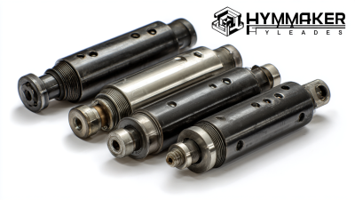
Choosing the right Hydraulic Cylinder Bore is a practical engineering decision, not a simple catalog exercise. Global buyers must match bore diameter with working pressure, required force, stroke length, mounting style, and available installation space. A 40 mm bore may suit a compact material-handling unit, while a 100 mm bore could be necessary for a demanding press or loader application.
Hydraulic engineering author Harry L. Merritt expressed a useful design principle: “Cylinder selection depends on force, motion, and control—not force alone.” That point still matters in 2026. A larger bore can increase pushing force, but it may also reduce operating speed and raise oil consumption. The wrong choice can leave a machine slow, overheated, or unexpectedly difficult to control.
This guide examines common bore sizes used by international equipment manufacturers and replacement buyers. It considers metric standards, imperial equivalents, pressure ratings, rod diameter, and real installation limits. For example, a 63 mm bore cylinder may appear suitable on paper, yet a narrow frame could reject its larger body or mounting brackets. Small details matter.
The recommendations are practical, but not absolute. Supplier standards differ. Application data can be incomplete. Buyers should verify force calculations, duty cycles, seal materials, and testing requirements before ordering. Even experienced engineers sometimes select a familiar bore too quickly. That deserves a second look. A reliable Hydraulic Cylinder Bore decision balances performance, service life, cost, and compatibility across markets.
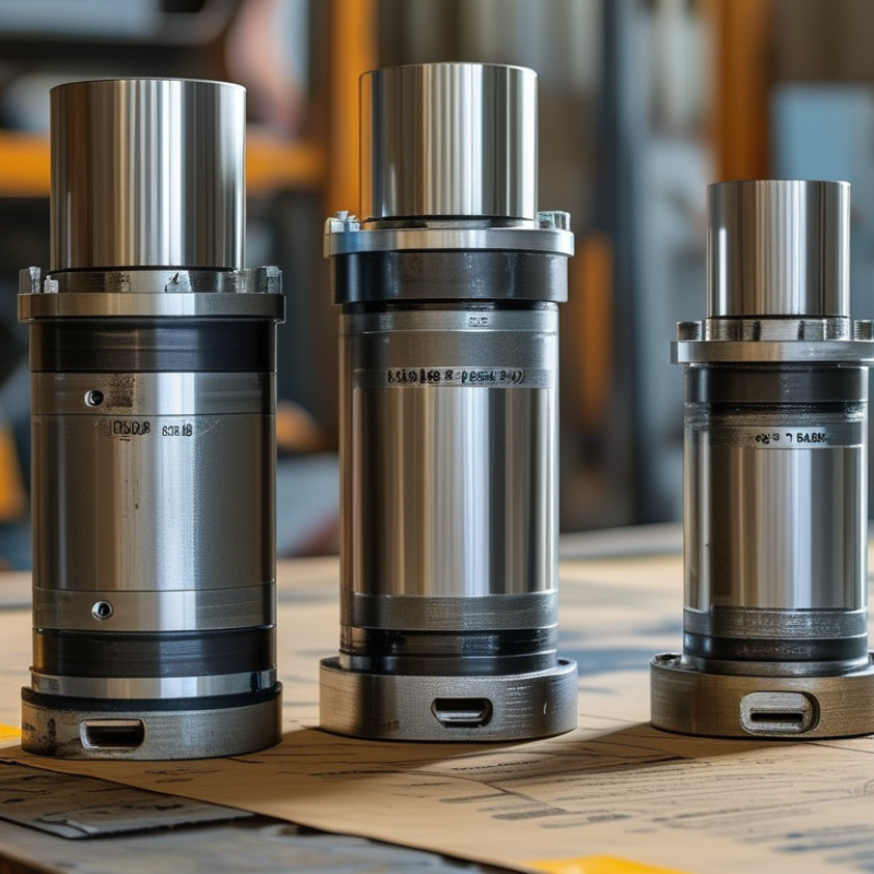
Hydraulic cylinder bore size means the barrel’s internal diameter. It determines piston area, oil volume, force, and response speed. Larger bores create greater pushing force at the same pressure. They also require more oil and may reduce operating speed. Common metric bore sizes include 25, 32, 40, 50, 63, 80, 100, 125, and 160 millimeters. The best size depends on load, pressure, stroke, installation space, and duty cycle.
Force is calculated by multiplying pressure by piston area. The basic formula is F = P × A. Rod-side pulling force is lower because the rod occupies part of the piston area. This detail is often missed during early purchasing discussions. A 63-millimeter bore may suit compact equipment, while an 80 or 100-millimeter bore may handle heavier loads. Bigger is not automatically better.
Measure safely with the hydraulic system fully depressurized. Clean the barrel opening before taking readings. Use an internal micrometer or telescoping gauge for accurate bore measurements. A caliper can help, but its jaws may not reach the true diameter. Measure at several positions and angles. Compare the results against the drawing, not only the nameplate. In field inspections, I have found worn barrels reading slightly larger near the opening. That small difference can affect sealing and leakage. I once treated a rough measurement as final; it was not. Allow for manufacturing tolerance, coating thickness, temperature, and seal condition when selecting a replacement cylinder.
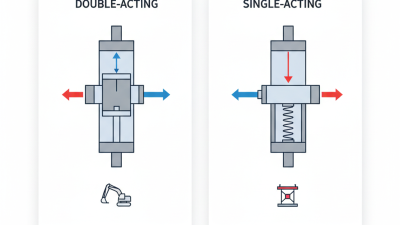
Global hydraulic applications commonly use bore sizes from 25 to 200 mm. The most practical choices include 32, 40, 50, 63, 80, 100, 125, and 160 mm. In North American projects, 2-inch, 2.5-inch, 3-inch, and 4-inch bores remain familiar. Metric sizes often simplify sourcing across international manufacturing networks.
Bore selection begins with required force, working pressure, stroke, and installation space. A 63 mm bore suits many compact industrial actuators. An 80 or 100 mm bore provides greater force for lifting, forming, and mobile machinery.
Engineers should calculate force using piston area, not bore diameter alone. Small mistakes here become expensive.
According to Grand View Research, construction and material handling remain major demand sectors in the global hydraulic cylinder market. MarketsandMarkets also reports continued growth in mobile hydraulics, driven by infrastructure and agricultural equipment. These findings support the popularity of medium bores, especially 50–100 mm.
ISO 6020/2 and ISO 6022 provide useful dimensional references for medium- and heavy-duty cylinders. However, standards do not replace application testing. A 100 mm cylinder may fit the force calculation but fail through side loading, poor mounting, or insufficient rod strength.
Real installations are less tidy. Engineers should review pressure peaks, temperature, seals, and available replacement parts before finalizing the bore.
Selecting the right hydraulic cylinder bore starts with force, not catalog habit. Use F = p × A, then divide required force by available pressure. A 50 mm bore produces about 98 kN at 500 bar, before efficiency losses. A 63 mm bore produces roughly 156 kN under the same pressure. These figures explain why 50, 63, 80, 100, and 125 mm bores remain common global choices. Smaller 25 and 32 mm bores suit compact automation, while 160 mm and larger sizes serve heavy equipment. Grand View Research’s 2024 hydraulic cylinder report forecasts approximately 4.8% market growth through 2030, reflecting demand for carefully sized systems.
Do not size by force alone. Check required speed, oil flow, rod diameter, stroke, mounting alignment, and buckling risk. A 100 mm bore moving at 0.2 m/s requires about 94 liters per minute, ignoring leakage. That flow may exceed a small power unit’s practical capacity. ISO 6020-2 provides dimensional guidance for medium-duty cylinders, but it does not replace application testing. I usually add a modest force margin, often 10–20%, after calculating real load peaks. Too much margin can create unnecessary mass, cost, and slower movement. That is an easy mistake.
Environmental conditions also change the decision. Side loading, cold oil, frequent impact, and long unsupported strokes can justify a larger rod or guided mounting. NFPA fluid power industry statistics continue to identify mobile equipment and industrial machinery as major demand areas. Field measurements matter more than a clean spreadsheet. Verify pressure at the cylinder port, not only at the pump outlet.
The table below compares commonly specified hydraulic cylinder bore sizes. Theoretical extension forces are calculated from piston area and system pressure before subtracting friction, back pressure, mechanical losses, and any required safety margin.
| Bore Size (mm) |
Piston Area (cm²) |
Theoretical Extension Force at 160 bar (kN) |
Theoretical Extension Force at 210 bar (kN) |
Typical Operating Requirement | Common Equipment Examples | Selection Guidance |
|---|---|---|---|---|---|---|
| 25 | 4.91 | 0.79 | 1.03 | Light-duty positioning, compact clamping, and small control movements | Small fixtures, laboratory equipment, compact automation | Use when installation space is limited and the required force is low. |
| 32 | 8.04 | 1.29 | 1.69 | Light lifting, guiding, indexing, and low-load linear actuation | Small material-handling units, compact agricultural mechanisms | Confirm that the rod and mounting hardware can withstand side loads. |
| 40 | 12.57 | 2.01 | 2.64 | Low-to-medium force applications with moderate duty cycles | Packaging machinery, compact presses, small lifting devices | A practical choice when a compact cylinder is needed for loads up to a few kilonewtons. |
| 50 | 19.63 | 3.14 | 4.12 | General-purpose actuation and moderate clamping or lifting | Industrial fixtures, conveyors, compact construction attachments | Allow additional capacity for friction, acceleration, and shock loading. |
| 63 | 31.17 | 4.99 | 6.55 | Medium-duty lifting, pushing, and tilting operations | Mobile equipment, agricultural machinery, general industrial systems | Often suitable for medium loads where a balanced size-to-force ratio is required. |
| 80 | 50.27 | 8.04 | 10.56 | Medium-to-heavy duty movement and higher clamping force | Material handling, compact excavator functions, industrial presses | Check buckling risk for long strokes and select the rod diameter accordingly. |
| 100 | 78.54 | 12.57 | 16.49 | High-force lifting, pressing, and structural positioning | Construction machinery, forming equipment, heavy-duty conveyors | Suitable when operating force is more important than compact packaging. |
| 125 | 122.72 | 19.64 | 25.77 | Heavy-duty actuation with substantial load capacity | Large agricultural equipment, industrial presses, lifting platforms | Verify mounting strength, pin bearing stress, and hydraulic flow requirements. |
| 160 | 201.06 | 32.17 | 42.22 | High-load lifting, pushing, and controlled movement | Large mobile machinery, heavy material handling, steel-processing equipment | Use detailed structural calculations for long-stroke or high-cycle applications. |
| 200 | 314.16 | 50.27 | 65.97 | Very high-force applications and large structural movements | Heavy presses, large lifting systems, mining and infrastructure equipment | Review system relief pressure, rod buckling, load alignment, and mounting deflection. |
| 250 | 490.87 | 78.54 | 103.08 | Extreme-force lifting, pressing, and heavy-duty mechanical control | Large presses, shipyard equipment, heavy industrial machinery | Confirm available pump flow and ensure the structure can transmit the cylinder force. |
| 320 | 804.25 | 128.68 | 168.89 | Exceptional force requirements in large-scale industrial systems | Heavy lifting installations, large forming systems, infrastructure machinery | Use only after complete checks of pressure, flow, stability, fatigue, and mounting loads. |
For global buyers in 2026, cylinder bore selection starts with standards, not catalog popularity. Common metric bores include 25, 32, 40, 50, 63, 80, and 100 mm. Larger sizes often follow manufacturer series rather than one universal table. ISO 6020/2 and ISO 6022 provide useful dimensional frameworks, but they do not make every cylinder interchangeable. That distinction matters.
A bore tolerance controls the finished internal diameter and affects piston sealing, friction, and service life. Suppliers should state bore tolerance, honed surface condition, roundness, and straightness on technical drawings. A polished tube can still fail if its geometry is inconsistent. Ask for inspection records, not only a tolerance number. In practice, measured results often reveal variations between production lots. This is where my own sourcing reviews changed: a close nominal size does not guarantee reliable performance.
International compatibility also depends on rod diameter, mounting dimensions, port threads, seal materials, and operating pressure. Metric and inch threads can look similar and still create costly installation problems. Confirm every interface before ordering. Request a cross-sectional drawing, material certificate, pressure rating, and dimensional inspection report. Allow space for thermal expansion and local maintenance tools. A 63 mm bore may fit the force calculation, yet fail the machine envelope. Recheck the calculation. Good engineering leaves room for uncertainty when standards, tolerances, and supplier practices differ across regions.
Common nominal bore sizes used in international hydraulic cylinder design, shown in millimetres with inch conversions for global procurement and system compatibility.
Reference framework: ISO 6020-2 and ISO 6022 nominal cylinder size series. Actual availability and dimensional tolerances may vary by cylinder design and application.
Bore size determines theoretical pushing force, but it should not decide a purchase alone. Fortune Business Insights estimated the global hydraulic cylinder market at about USD 15.2 billion in 2024, with construction, agriculture, and material handling supporting demand. These sectors often require different bore choices, even at similar working pressures.
Use the equation: force equals pressure multiplied by piston area.
At 210 bar, a 100 mm bore produces roughly 165 kN theoretically. An 80 mm bore produces about 106 kN. The difference is substantial. However, real output falls because of seal friction, pressure losses, and installation conditions. Common metric bore steps include 63, 80, 100, 125, and 160 mm. They are useful comparison points, not automatic answers.
Check the load profile before choosing the largest cylinder. A larger bore may increase force, but it can reduce speed, require more oil, and enlarge the mounting structure. Review rod buckling, stroke length, side loading, duty cycle, and available pump flow. ISO 6020/2 and ISO 6022 provide useful dimensional references for medium- and high-pressure cylinders. Field testing still matters. A clean calculation can miss vibration, misalignment, or cold-start behavior. I would compare the smallest bore meeting peak force with the next size above it, then verify safety margins under actual pressure. Bore selection is rarely perfect on the first spreadsheet.