Choosing the right Hydraulic Cylinder Types in 2026 requires more than comparing pressure ratings or purchase prices. The cylinder must match the machine’s load, stroke length, mounting position, speed, and working environment. A compact loader may need a double-acting cylinder for controlled movement in both directions. A lifting platform may demand a stronger design, stable guidance, and reliable load-holding protection. Small details matter. A dusty construction site, a cold warehouse, or a salt-exposed port can change the best choice.
This guide examines common options, including single-acting, double-acting, telescopic, tie-rod, welded, and custom cylinders. It considers practical factors such as bore diameter, rod strength, seal materials, cushioning, maintenance access, and hydraulic-fluid compatibility. These decisions should be checked against manufacturer data and real operating conditions, not assumptions. In field inspections, a leaking seal often reveals poor alignment, excessive side loading, or neglected maintenance rather than a simple cylinder fault. That lesson is easy to overlook.
Performance also depends on the complete hydraulic system. A well-selected cylinder can still work poorly when the pump, valve, hose, or control settings are unsuitable. Engineers should review duty cycles, peak loads, safety margins, and expected service life before approving a design. There is no universal best type. Sometimes, a lower-cost cylinder creates higher replacement costs later. This guide offers a practical framework, while recognizing that unusual applications may require specialist testing and a second review. Industry standards and supplier documentation should support the final decision.
Choosing a hydraulic cylinder in 2026 starts with four measurable demands: load, stroke, speed, and pressure. Do not select by bore alone. Calculate the working load, then check starting force and friction. For vertical lifting, include gravity and the weight of attached tooling. Side loads need guides, not wishful thinking. Specify stroke from actual travel, including end clearance and alignment changes. An extra 50 millimeters may prevent a costly mechanical stop.
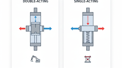
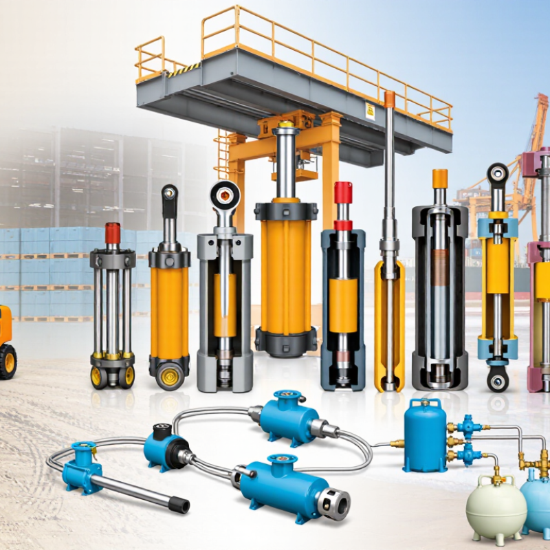
Speed determines oil flow and valve capacity. Use flow equal to piston area multiplied by velocity. Then verify pump delivery under load. Single-acting cylinders suit powered movement with a gravity or spring return. Double-acting cylinders provide controlled motion in both directions. Telescopic cylinders fit limited installation length, but their stages require careful stability checks. Rod cylinders work well for long, controlled strokes when mounting space allows. Do not ignore duty cycle. Heat and contaminated oil can shorten seal life.
Pressure ratings deserve conservative judgment. At pressures up to 70 MPa, every hose, fitting, valve, and mounting part must match the verified working pressure. Use the safety margin required by the application and relevant standards. Proof testing belongs to qualified personnel with guarded equipment. I have seen neat calculations fail when buckling and eccentric load were omitted. Recheck rod diameter, pin stresses, retraction force, and mounting alignment. Real machines are less tidy than drawings. Record every assumption before ordering.
Use the application load, available installation space, required stroke, operating speed, duty cycle, and maximum working pressure to narrow the cylinder type. Values below are typical engineering ranges and must be verified against the selected cylinder design and applicable safety requirements.
| Hydraulic Cylinder Type | Typical Bore Range | Typical Working Pressure | Practical Load Capability | Typical Stroke Range | Typical Operating Speed | Common Mounting or Application | Primary Selection Advantage | Key Limitation or Check |
|---|---|---|---|---|---|---|---|---|
| Tie-Rod Cylinder | 25–200 mm | 7–21 MPa | Approximately 4–660 kN at 21 MPa, based on the cap-end piston area | 50–3,000 mm | 0.10–0.50 m/s | Industrial automation, material handling, light and medium machinery | Easy maintenance and widely available standard dimensions | Less suitable for severe contamination or very high pressure unless specifically reinforced |
| Welded-Body Cylinder | 40–320 mm | 21–35 MPa | Approximately 110–2,815 kN at 35 MPa, based on the cap-end piston area | 100–4,000 mm | 0.10–0.60 m/s | Mobile equipment, construction machinery, agricultural machinery, compact installations | Shorter overall length and strong resistance to external contamination | Internal servicing can be more difficult than with a removable tie-rod design |
| Mill-Duty Cylinder | 50–500 mm | 21–35 MPa | Approximately 69–6,872 kN at 35 MPa, based on the cap-end piston area | 100–6,000 mm | 0.05–0.50 m/s | Steel processing, presses, heavy industrial production lines, high-cycle machinery | High structural strength, long service life, and strong side-load protection options | Usually heavier, larger, and more expensive than general-purpose cylinders |
| Compact Cylinder | 20–100 mm | 16–35 MPa | Approximately 5–275 kN at 35 MPa, based on the cap-end piston area | 10–500 mm | 0.05–0.30 m/s | Clamping, tooling, packaging equipment, restricted installation spaces | Small installation envelope and short retracted length | Shorter bearing length and limited stroke-to-bore combinations may reduce side-load tolerance |
| Telescopic Cylinder | 50–400 mm first-stage bore | 16–25 MPa | Approximately 49–1,257 kN at 25 MPa, based on the first-stage cap-end area | 500–10,000 mm | 0.05–0.30 m/s | Dump bodies, lifting platforms, tipping equipment, applications requiring long extension | Very long stroke from a comparatively short retracted length | Load capacity and buckling resistance vary by stage; side loading should be minimized |
| Single-Acting Plunger Cylinder | 50–500 mm | 25–70 MPa | Approximately 55–13,744 kN at 70 MPa, based on the cap-end area | 50–3,000 mm | 0.01–0.20 m/s | Heavy lifting, jacking, presses, return-by-load applications | High pushing force with a simple hydraulic circuit | Return force is normally supplied by gravity, a spring, or an external mechanism |
| High-Pressure Double-Acting Cylinder | 20–160 mm | 40–70 MPa | Approximately 22–1,407 kN at 70 MPa, based on the cap-end piston area | 25–2,500 mm | 0.05–0.50 m/s | Hydraulic intensifiers, specialized presses, compact high-force systems | High force density where pressure up to 70 MPa is required | Requires pressure-rated tubing, fittings, valves, seals, mounting, and guarding |
Load calculation: Theoretical pushing force is calculated as F = p × A, where F is force in newtons, p is pressure in pascals, and A is piston area in square metres. Actual output should be reduced for friction, pressure losses, seal drag, acceleration, side loads, and the required safety factor. Retraction force is lower because the rod area is subtracted from the piston area. The stated pressure values are typical working-pressure ranges, not burst-pressure ratings.