Blog

How to Choose the Right Hydraulic Cylinders

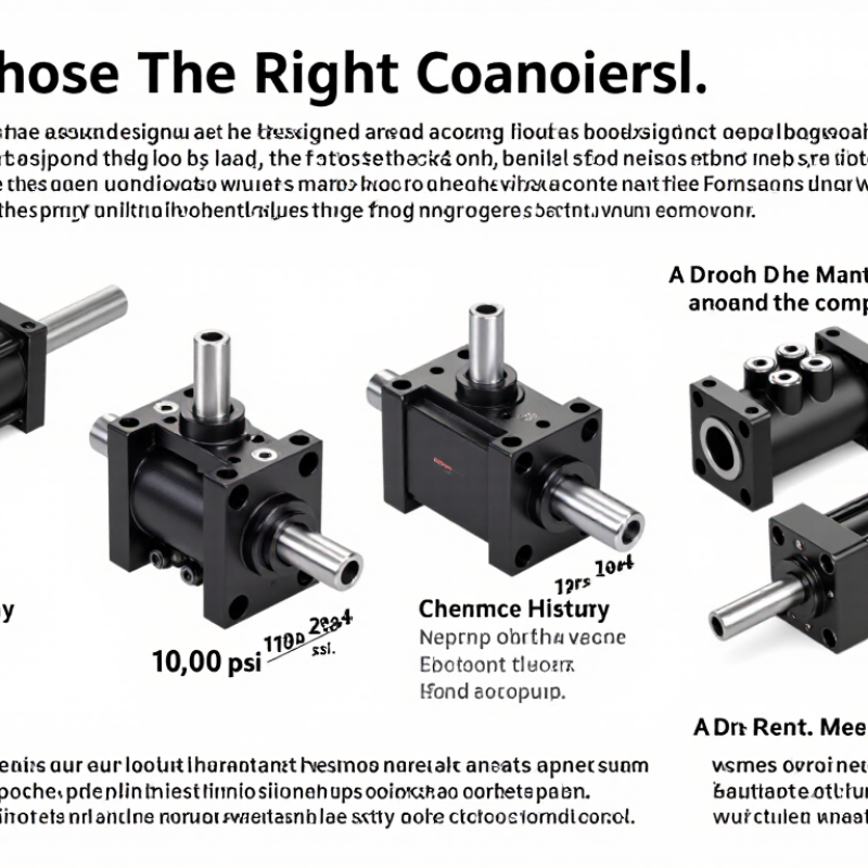
Choosing the right Hydraulic Cylinders begins with the machine’s real working conditions, not a catalogue picture. Load, stroke length, operating pressure, speed, mounting style, and available space must agree. A cylinder rated for 10,000 psi may still fail when side loading bends its rod. Small details matter.

Dr. Noah D. Manring, a respected hydraulic systems researcher and author, states, “A hydraulic system should be designed around the load, not around the component.” This principle keeps selection practical. Measure the force at startup, during motion, and at the end of the stroke. Check the fluid temperature, contamination level, and duty cycle. A loader working outdoors needs different seals from an indoor packaging machine. Chrome thickness, rod diameter, cushioning, and port location also deserve attention. Ignore one detail, and maintenance costs can rise quickly.

There is no perfect cylinder.

Even experienced engineers can choose poorly when they trust average conditions. Real machines vibrate, drift, heat up, and face uneven loads. Therefore, compare manufacturer data with field measurements and service history. Confirm retraction force, extension force, buckling risk, and mounting alignment. Ask whether replacement seals and rods are readily available. A lower purchase price may hide shorter service life. The best choice balances performance, reliability, safety, and future maintenance. It may not be the largest or strongest option. It should be the most suitable one.
How to Choose the Right Hydraulic Cylinders

Define the Application Requirements for a Hydraulic Cylinder

Choosing the right hydraulic cylinder begins with defining the application, not selecting a bore size. Record the load, stroke, speed, duty cycle, mounting position, and available pressure. A cylinder lifting 8,000 kilograms needs different safety margins from one controlling a light conveyor gate. Calculate force with F = P × A, then include friction, side loading, and acceleration. Do not size only from maximum pressure. That shortcut often causes premature seal wear.

Grand View Research reported that the global hydraulic cylinder market was valued at approximately USD 14.7 billion in 2023. This growth reflects demand across construction, agriculture, and material handling. However, market data cannot replace field measurements. ISO 4413 emphasizes safe hydraulic-system design, including pressure control, hose routing, and protection against unexpected movement.

During site assessments, check oil temperature, contamination risk, corrosion, and available space around the rod. A compact cylinder may fit neatly, but poor maintenance access can become an expensive weakness.

Tip: Write the operating profile before requesting quotations. Include peak and continuous loads, cycle frequency, stroke length, rod orientation, and environmental exposure. Leave room for uncertainty. Real machines rarely behave perfectly. Recheck calculations after testing, because vibration, uneven loading, and temperature changes may reveal assumptions that looked reasonable on paper.
Match Cylinder Type, Force, Stroke, and Speed to the Task

How to Choose the Right Hydraulic Cylinders

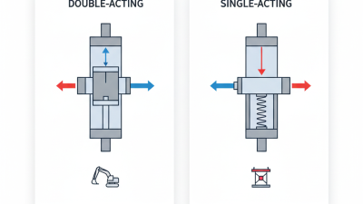
Choosing a hydraulic cylinder starts with the task, not the catalog. A double-acting cylinder suits equipment that needs controlled movement in both directions. A single-acting cylinder may work for lifting, clamping, or returning by gravity. Telescopic cylinders fit tight spaces, but their extended sections can be more sensitive to side loading. I have seen installations fail because the cylinder type was chosen before the movement was studied.

Match force to the real load. Use the required force, pressure, and piston area, then add a practical safety margin. Force equals pressure multiplied by piston area. Remember that retracting force is lower because the rod occupies part of the piston area. Stroke must cover the full travel without bottoming out. Add physical stops where possible. Do not use the cylinder as a structural guide.

Speed depends mainly on oil flow and cylinder area. A wider bore usually moves more slowly at the same flow, while a smaller bore may increase speed but reduce force. Check the pump’s actual flow, not only its rated value. Pressure losses in hoses, valves, and fittings can be significant. The rod diameter also matters when compression loads create buckling risk. Measure the mounting points carefully; a few millimeters of misalignment can cause seal wear. My own calculations have sometimes looked perfect, yet field movement was uneven. Temperature, contamination, and changing loads were missing from the first estimate. Test the cylinder under realistic conditions before final installation.

How to Choose the Right Hydraulic Cylinders

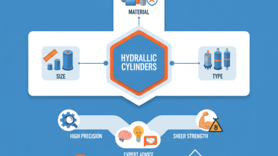
Match cylinder type, force, stroke, and speed to the task.

The chart shows the theoretical extension force available from common cylinder bore sizes at 160 bar system pressure, calculated from piston area and pressure. Select a cylinder type that suits the motion, choose a bore that exceeds the required load with a safety margin, specify a stroke that covers the full travel, and verify that the required operating speed is within the cylinder’s flow and stability limits. Actual output may be lower because of friction, pressure losses, and efficiency.

Select Suitable Materials, Seals, and Operating Specifications

How to Choose the Right Hydraulic Cylinders

Choosing a hydraulic cylinder starts with the working environment, not the catalog photograph. Identify the fluid, pressure, temperature, load direction, stroke, and cycle frequency. Carbon steel suits many indoor systems and offers practical strength. Stainless steel performs better near moisture, chemicals, or frequent washing. The piston rod also matters. A corrosion-resistant surface can prevent scoring, but it may not solve poor alignment. Material choice needs a complete view.

Seal selection should follow fluid compatibility and temperature limits. Nitrile seals often suit standard mineral-based fluids and moderate temperatures. Polyurethane handles abrasion well, especially in mobile equipment. Fluorocarbon compounds can tolerate higher heat and aggressive fluids, but they are not automatically the best choice. Check the seal supplier’s actual data. Small differences matter.

Operating specifications deserve equal attention. Confirm rated pressure, peak pressure, rod diameter, mounting style, and required safety margin. Calculate the force on both extension and retraction. Account for side loads, uneven mounting, and pressure spikes. Control rod speed to reduce heat and seal wear. Clean fluid is essential. Field inspections often find contamination inside otherwise well-designed systems. That mistake is expensive. I would recheck the calculations after installation, because real loads rarely match the first estimate. Leave room for temperature changes, maintenance access, and imperfect alignment.

Verify Mounting, Hydraulic Compatibility, and Safety Factors

Choosing the right hydraulic cylinder starts with the mounting arrangement, not the bore size. Measure pin diameter, center-to-center length, and available clearance. A clevis mount needs proper pin alignment and side support. A misaligned cylinder can wear seals quickly and bend the rod. Check the retracted and extended positions before ordering. Small errors become expensive repairs.

Hydraulic compatibility matters just as much. Confirm the system pressure, flow rate, operating temperature, and fluid type. The cylinder’s rated pressure should exceed the machine’s maximum working pressure. Add a suitable safety factor for shock loads, uneven lifting, and frequent cycling. Do not treat the catalog rating as a permanent guarantee. Actual loads can be less predictable. Inspect hoses, ports, and fittings for matching thread standards and pressure ratings. A fitting that almost matches is still a failure risk.

Tips: Sketch the mounting points. Record every measurement twice. Ask a qualified engineer to review unusual loads or suspended applications. During testing, use low pressure first and watch for drift, leaks, noise, or uneven movement. I have found that rushed measurements cause more trouble than complex calculations. One detail is easy to miss: side loading may not appear until the machine reaches full extension. Recheck it under realistic working conditions.

How to Choose the Right Hydraulic Cylinders - Verify Mounting, Hydraulic Compatibility, and Safety Factors
Selection Dimension What to Verify Representative Engineering Data Recommended Check Safety Consideration
Mounting Configuration Confirm whether the cylinder uses a clevis, flange, trunnion, foot, spherical-eye, or other mounting arrangement. Clevis mounts generally permit pivoting at one end. Flange and foot mounts provide a more rigid attachment and require accurate alignment. Match the cylinder mounting type and dimensions to the machine drawing, including pin diameter, mounting width, bolt pattern, and available clearance. Do not use a rigid mount where the mechanism requires angular movement unless the design includes an appropriate joint or alignment system.
Alignment and Side Load Check whether the cylinder rod will remain concentric with the applied load throughout the complete stroke. Hydraulic cylinders are primarily designed for axial loading. Side loads can increase rod, bearing, seal, and tube wear. Use a guided load, spherical bearing, or mechanical linkage when the load path can create transverse force or bending moment. Never rely on the cylinder rod alone to guide a moving structure unless the cylinder and application are specifically engineered for that duty.
Required Force Calculate the force needed during extension and retraction, including load weight, friction, acceleration, and external resistance. Extension force is based on the full piston area. Retraction force is based on the annular area after subtracting rod area.
F = P × A
Select a bore that provides the required force at the actual minimum operating pressure, not only at the system relief setting. Include a suitable design margin for uncertain loads, friction changes, pressure losses, and dynamic effects. The margin must be justified by the risk assessment.
Bore and Rod Diameter Verify piston area, rod strength, buckling resistance, bearing load, and available installation space. A larger bore increases force. A larger rod improves column strength and reduces the annular area available for retraction. Check both extension and retraction performance. For compression loading, evaluate rod buckling using the actual stroke, end conditions, and mounting arrangement. Long, slender rods under compression require particular attention to buckling; do not size the rod from tensile force alone.
Stroke Length Confirm the required travel, end positions, mechanical stops, and installation length. The usable stroke should meet the machine movement without forcing the cylinder to act as a structural stop. Compare retracted length, extended length, pin-to-pin dimensions, and clearance at both ends of travel. Use external mechanical stops or cushioning where appropriate. Avoid repeatedly bottoming out the piston unless the cylinder is designed for that condition.
Pressure Rating Compare the cylinder's rated working pressure with normal pressure, peak pressure, and relief-valve settings. Common industrial hydraulic systems may operate around 70 to 210 bar, but cylinder ratings vary and must be verified from the technical specification. Ensure the cylinder's rated working pressure is at least equal to the highest intended pressure, including transient spikes. The relief-valve setting must not exceed the lowest pressure rating of the cylinder, hose, fittings, valves, and connected components.
Proof and Burst Safety Review the manufacturer's proof-test pressure, burst rating, fatigue data, and applicable design standard. A proof pressure of approximately 1.5 times rated working pressure is common in some cylinder specifications, but it is not universal. Use the specified proof and burst values for the exact cylinder design; do not infer them solely from nominal working pressure. Proof pressure is a test level, not a permitted operating pressure. Apply a documented safety factor for static, dynamic, fatigue, and failure-mode risks.
Hydraulic Fluid Compatibility Identify the fluid type, viscosity range, operating temperature, additives, and contamination conditions. Mineral-oil hydraulic fluids are common, while water-glycol, biodegradable fluids, and fire-resistant fluids may require different seal and coating materials. Confirm compatibility of seals, rod coating, tube material, fittings, hoses, and lubricants with the selected fluid. Do not substitute a different fluid without checking seal compatibility, swelling or shrinkage risk, lubrication properties, and temperature limits.
Temperature Range Check minimum and maximum fluid and ambient temperatures during start-up, continuous operation, and storage. Seal performance, fluid viscosity, clearances, and damping behavior can change significantly with temperature. Compare the complete temperature range with the limits for the seals, fluid, wiper, coating, and cushioning system. Low temperatures can cause sluggish movement and high pressure losses; high temperatures can accelerate seal aging and reduce fluid viscosity.
Port Size and Hydraulic Flow Verify port thread or flange type, port location, hose size, required flow rate, and allowable pressure drop. Cylinder speed is related to flow and piston area.
v = Q ÷ A
Calculate extension and retraction speeds separately because the effective areas are different. Check hose velocity and pressure loss. Overspeed, pressure spikes, and unstable movement can occur if flow control, counterbalance, or load-holding functions are inadequate.
Cushioning and End-of-Stroke Control Determine whether the cylinder needs adjustable cushions, external shock absorbers, flow controls, or deceleration valves. Cushioning dissipates kinetic energy near the end of the stroke and can reduce impact loads and noise. Estimate moving mass, velocity, stopping distance, and cycle frequency before selecting the cushion arrangement. Do not use cushioning to compensate for an incorrectly sized cylinder, excessive speed, or an uncontrolled load.
Load Holding and Failure Control Assess the consequences of hose rupture, valve leakage, power loss, or loss of hydraulic pressure. Depending on the application, a pilot-operated check valve, counterbalance valve, hose-burst valve, or mechanical locking device may be required. Define the safe position of the load and select a load-control method that remains effective under the identified failure conditions. For suspended or hazardous loads, never depend solely on trapped hydraulic pressure for personnel protection or positive load retention.
Environment and Corrosion Consider moisture, salt spray, dust, chemicals, washdown, outdoor exposure, and abrasive contaminants. Rod coating, wiper design, seal material, fastener finish, and drainage provisions affect service life. Specify environmental protection for the rod, tube, mounting hardware, and connections based on the actual exposure conditions. Protect the rod from impact and contamination. A damaged rod surface can rapidly damage seals and cause external leakage.
Installation and Commissioning Confirm clean hydraulic assembly, correct hose routing, correct bleeding procedure, and secure fasteners. Air in the circuit can cause erratic motion, compressibility effects, noise, and shock loading. Flush the system to the required cleanliness level, inspect fittings, bleed trapped air where permitted, and test at low pressure before full operation. Use guards and safe exclusion zones during first movement. Check for leakage without placing hands near a suspected high-pressure jet.
Maintenance and Inspection Establish inspection intervals for leakage, rod damage, mounting wear, loose hardware, hose condition, and abnormal temperature or noise. External leakage, uneven wear, drifting, or slower movement can indicate seal damage, contamination, misalignment, or valve problems. Record operating pressure, temperature, cycle count, symptoms, and corrective actions to identify changes over time. Depressurize and isolate the system before maintenance. Hydraulic accumulators and trapped pressure must also be safely discharged.
Engineering values shown are representative guidance only. Final cylinder selection must be verified against the exact load cases, duty cycle, mounting geometry, hydraulic circuit, applicable regulations, and the technical data for the selected cylinder.

Compare Maintenance Needs, Service Life, and Total Cost

Choosing a hydraulic cylinder by purchase price alone can create expensive surprises. The U.S. Department of Energy’s Improving Pumping System Performance report notes that inefficient fluid-power systems can waste substantial energy through leakage, heat, and poor control. A cylinder with worn seals may look functional while increasing pump loading and cycle time. Check seal quality, rod protection, contamination tolerance, and access for inspection before comparing quotations.

Maintenance records should show seal replacement intervals, oil contamination events, alignment checks, and unplanned downtime. ISO 4413 recommends controlling contamination, pressure, and mechanical hazards throughout a hydraulic system. In practice, clean oil and correct alignment often extend service life more effectively than heavier construction. Still, this is not guaranteed. Harsh water, side loading, and shock loads can defeat an otherwise well-specified cylinder.

Calculate total cost over the planned service period. Include purchase, installation, replacement seals, labor, lost production, energy, and disposal. The U.S. Department of Energy’s Operations and Maintenance Best Practices guide reports that preventive maintenance can reduce downtime and improve equipment reliability, but results vary by application. A simple estimate is useful: a 900-dollar cylinder needing two major repairs may cost more than a 1,300-dollar unit lasting longer. Yet service-life claims deserve evidence. Request field data, test conditions, warranty limits, and maintenance assumptions. A spreadsheet cannot fully price a failed shift.